Wednesday, November 10, 2010

555 Based Simple Servo Controller

Servos are very useful devices for a number of projects, such as robotics, automation or just remotely controlling something, eg model car steering. They are relatively cheap and easy to get hold of, but controlling them is a little tricky as they requrie precise timing to command the output to move to a desired location.
Most servos have a 50Hz refresh rate (20ms) at which point a pulse of between 1 and 2ms is used to command the output to move between -45degrees and +45degrees.
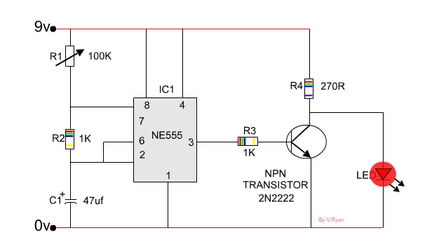
A 555 timer can be used to command the output with a simple circuit and adjusted using a potentiometer.

Circuit diagram:


Click to Enlarge

The circuit is pretty self explanatory. We use a 555 timer IC to generate a pulse every 20ms with a duty cycle of between 5 and 10% (1-2ms). All the parts used are common components. You can drive multiple servos with the same signal using this circuit to all have the same output or build multiple driver circuits to command many servos to different outputs.
Servos operate with a voltage between 5 and 6V, do not exceed this or you will damage them. Whereas the 555 timer will operate up to 15V.
Also note that servos require alot of current when commanding them and also to hold a position under load, this can be up to a few amps! So make note of this when designing your power supply.
“The Beetle Robot”

The following article will show you how to build a simple robot, called “The Beetle Robot”,  It’s great for beginners and easy to do.
This is the Beetle Robot v. 3 you are going to build:
Image
Before starting, I suggest you to read the complete tutorials. This will greatly lower the chances of you making a mistake.

Tools Needed:

  • soldering iron Â
  • electronic solder
  • diagonal cutter
  • Mini glue gun

Components for the robot

  • 2x – small 1.5 Volts motors
  • 2x – small paperclips
  • 2x – big paperclips
  • 2x – batteries AAA or AA
  • 1x – battery holder AAA or AA
  • 1x – 2 cm of heat shrink
  • 1x – wooden pearl  (for the caster)
  • 1x – meter of electric wire
  • 2x – Sub-mini lever SPDT switches
    Image
Here are the serial numbers of the components and tools from RadioShack .
Component Number
soldering iron 64-2184
electronic solder 64-006
diagonal cutter 64-2951
1.5 Volts motor 273-223
battery holder 270-398
SPDT switch 275-016
Most of the components can be bought for much cheaper at Digi-Key, Jameco, or similar.
At RobotShop you can find the dual AA battery holder and the small DC motor. You can find these components at any good electronic store.
Here is all the parts for the construction the beetle robot.
Image
1. Cut the electric wire in pieces of 6 cm each, 13 times.
Image
Strip 1 cm at each end.
Image
2. Regroup all the components.
Image

3. Solder each wire to each components except the two batteries.
Image
4. Take the battery holder and make a connection to the connection.
Image
This will give a third connection.See picture below.
Image
The blue wire is the third connections
Image
5. Turn the battery holder up side down so the batteries point to the ground. Glue the two switches on the battery holder in a V form.
Image
Image
Image
6. Glue the motor beside each switch so that the shaft touches the ground
Image
Image
Image
7. Take the big paperclip and make the caster like the picture below.
Image
You can make a nice looking caster or a normal one
Image
Image
I prefer the nice one
Image
8. How to make the connection
Image
Image
Image
9. Take the small paper clip and bend them to make antenna.
Image
Glue them to the switches and don’t put to much glue.
Image
Add 1 cm of heat shrink to the shaft of each motor.
Image
Image
10. Add the batteries in the battery holder and put it on a flat surface to see your creation take life. Congratulation!

Image
Image
Capacitance
Capacitance is typified by a parallel plate arrangement and is defined in terms of charge storage

 
where
  • Q = magnitude of charge stored on each plate.
  • V = voltage applied to the plates.
 Capacitors

Capacitors are the second most commonly used component in electronics. They can be thought of as tiny rechargable batteries -- Capacitors can be charged and discharged. The amount of charge that a capacitor can hold is measured in Farads or the letter F. However, 1F is too large for capacitors, so microfarads(µF) and picofarads(pF) are used. micro = 1/1,000,000 and pico = 1/1,000,000,000,000

So 100,000pF = 0.1µF = 0.0000001F

We will only be discussing two types of the most commonly used capacitors: Ceramic and Electrolytic.


  • Ceramic capacitors are brown and has a disc shape. These capacitors are non-polarized, meaning that you can connect them in any way. To find the value, you simply decode the 3 digit number on the surface of the capacitor. The coding is just like the resistor color codes except that they used numbers instead of colors. The first 2 digit are the significant figures and the third digit is the multiplier. These capacitors are measured in pF.

    ceramic capacitor image Schematic symbol


  • Electrolytic Capacitors has a cylinder shape. These capacitors are polarized so you must connect the negative side in the right place. The value of the resistor as well as the negative side is clearly printed on the capacitor. These capacitors are measured in µF.

    Capacitor Image Schematic symbol
 Resistor

Resistors are one of the most commonly used components in electronics. As its name implies, resistors resist the flow of electrons. They are used to add resistance to a circuit.

The color bands around the resistors are color codes that tell you its resistance value. Recall that resistance is measured in ohms.


Black=0,Brown=1,Red=2,Orange=3,Yellow=4,Green=5,Blue=6,Violet=7,Gray=8,White=9,Gold = 5% tolerance,Silver = 10% tolerance

Resistor: Brown, Black, Orange. Value = 10000 ohm or 10k
The tolerance bands indicates the accuracy of the values. A 5% tolerance (gold band) for example, indicates that the resistor will be within 5% of its value. For most applications, a resistor within 5% tolerance should be sufficient.

To get the value of a resistor, hold the resistor so that the tolerance band is on the right.

The first two color bands from the left are the significant figures - simply write down the numbers represented by the colors. The third band is the multiplier - it tells you how many zeros to put after the significant figures. Put them all together and you have the value.


NOTE: There are resistors with more bands and other types for specific applications. However, 4 band resistors(the ones discussed here) are the most common and should work for most projects.

One last important note about resistors is their wattage rating. You should not use a 1/4 watt resistor in a circuit that has more than 1/4 watt of power flowing.

For example, it is NOT okay to use a 1/4 watt resistor in a 1/2 watt circuit. However, it is okay to use a 1/2 watt resistor in a 1/4 watt circuit.

Schematic symbol
 Ohm's Law

Ohm's law is one of the most important concepts in electronics. Fortunately it's only a very simple mathematical relationship between current, voltage, and resistance.

According to the Ohm's law, voltage equals current times resistance which is expressed in the following equation:

E=IR
where E = voltage, I = current, and R = resistance

For example, if
I = 0.1A
R = 10k
then
E = 0.1 * 10k

E = 1000 volts


Note: "k" stands for "thousands". So 10k = 10,000 ohm
 Resistance

To better understand what resistance is, you must first get an idea of how electrons flow.

When an electron is knocked out of an atom, it will fly off and hit another atom. If the electron strikes the atom with enough force, it will knock off another electron. The atom that was just knocked off will hit another atom and so forth.

Animation of electron flow
Note that every time an electron strikes another, it is transferring its energy. Some of the energy is converted into heat every time it is transferred. The voltage will drop as the energy is transferred over long distances. Thus a long wire has a higher resistance than a short wire.

Some materials - such as copper and silver - does not hold on to its electrons very tightly. Therefore it doesn't require much energy to knock off an electron. These materials are called conductors and has a very low resistance to electron flow.

Materials such as clay and plastics hold on to their electrons more tightly than conductors. It takes more energy to knock off an electron from these materials. These materials are called insulators and has a high resistance to electron flow.


Now, you must understand that this is NOT how electrons really flow; It serves only as something for you to work with. To really know how electrons flow, which we will not get into, you will need to study quantum physics.

Resistance is represented by the letter R. The basic unit of measure is ohm or the symbol Ohm (Greek omega).

In the next section (Ohm's Law), we will show you the relationship between Current, Voltage, and Resistance. Resistance will also be further discussed as we introduce the resistor.
 Power

Power is simply the amount of energy used or the amount of "work" a circuit is doing.

Power is represented by the letter P. The basic unit for measuring power is watts or the letter W. To find power, all you need is a simple equation:
P=EI
or Power equals voltage times current.

For example, if
E = 9V
I = 0.5A
then
P = 9 * 0.5

P = 4.5W
<!--------------- END ---------------->
 Voltage


To make sense of voltage, we will need to make an analogy.

Lets imagine that electrons are represented by a marble on a flat plane. At this point, the plane is level and the marble does not move. If the plane is lifted at one side, the marble will roll down to the lower point.

illustration

In electricity, the high point is a point with lots of electrons and the low point is a point with a lack of electrons. The high point is called the high potential and the low point is the low potential. The difference between these two points is called the potential difference. The larger the potential difference, the larger the voltage.

illustration

Voltage can be thought of as the measure of the pressure pushing the electrons. The higher the pressure, the higher the voltage.

Voltage is represented by the letter E. The basic unit of measure is volts or the letter V. One volt will push 1 amp of current through 1 ohm of resistance. Resistance will be discussed in a later section. <!--------------- END ---------------->
Current

Electric current is the amount of electrons, or charge, moving past a point every second. It is basically the speed of electron flow. The faster the electron flow, the higher the current.


Current is represented by the letter I. The basic unit for measuring current is ampere. Ampere can be abbreviated to amp or just A.


1 amp = 1 coulomb/sec

Meaning for every amp, there are 6.25x10^18 electrons moving past a point every second.
Atoms and electrical charge


Atoms are the building blocks of all matter. They are made up of
protons, neutrons, and electrons. Every electron has a small negative
(-) charge. The proton has the same amount of charge except that it is
the opposite, positive (+) charge. Neutrons are electrically neutral
and have no charge. The protons and neutrons are located in the center
of atoms forming what is called the nucleus and the electrons revolve
around them.


It is very important to know that particles of
like charges will repel and unlike charges will attract. For example,
two protons or two electrons will repel each other. However, a proton
and a electron will attract. That is how the electrons are held inside
the atom. The attraction between the electrons and protons keeps the
electrons in orbit much like the gravitational attraction between the
sun and its planets.


Electricity is the flow of electrons so it is necessary to
measure the charge. The basic unit for measuring charge is the coulomb
or the letter C. 1 coulomb is equal to the charge of
6,250,000,000,000,000,000 electrons!!!


1C = 6.25x10^18 electrons

Friday, November 5, 2010

 NE 555 Astable circuit

Below is a typical 555 astable circuit that drives an LED. It is known as a LED flasher as the LED flashes on and off. The number of flashes per minute can be altered by turning the variable resistor.
Remember the 555 is activated by current at pin two and the output is through pin three. Altering the variable resistor alters the time between ‘pulses’ at pin three. The pulse at pin three switches the transistor which allows the LED to come on.
The LED flashes on and off because with this astable circuit the pulses from pin three are repeated until the power is switched off completely.

The LED flashes on and off because with this astable circuit the pulses from pin three are repeated until the power is switched off completely.